
Hardware engineering is currently facing an influx of "vibe coding" promises: upload your netlist to an opaque cloud model, let it "think", and get back a manufactured board without human intervention.
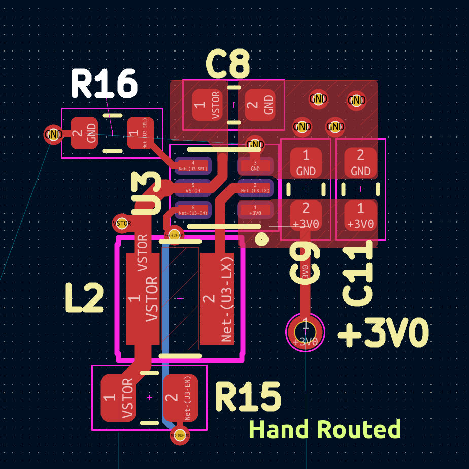
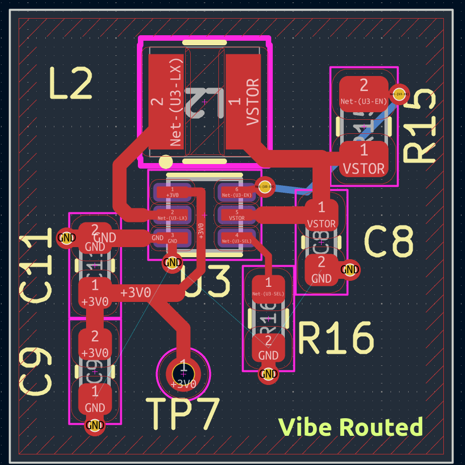
Earlier today, hardware engineer Alperen Akkuncu posted a side-by-side benchmark on X (@AlperenAkkuncu) comparing a hand-routed boost converter against Astra, an AI-based autorouter. His critique pointed straight at the physics:
"First off, I would never accept this vibe routed layout, the output capacitor placement is not good, it's very far apart from the GND and OUT pin of the converter which is very important for boost converters... What makes it unusable for me? It's so difficult to make incremental changes, everything takes lot of time. For instance, I tried to add the test point later and asked Astra to route it for me quickly, it took it 4 minutes which can take seconds."
We fed this exact test case into Fragua to dissect why unconstrained AI tools fall flat on power converters, and how Fragua pure-auto finishes the same Hand BOM (WLP-6, dual Cout, R15/R16) in ~15 ms with DRC 0 — no hand copper.
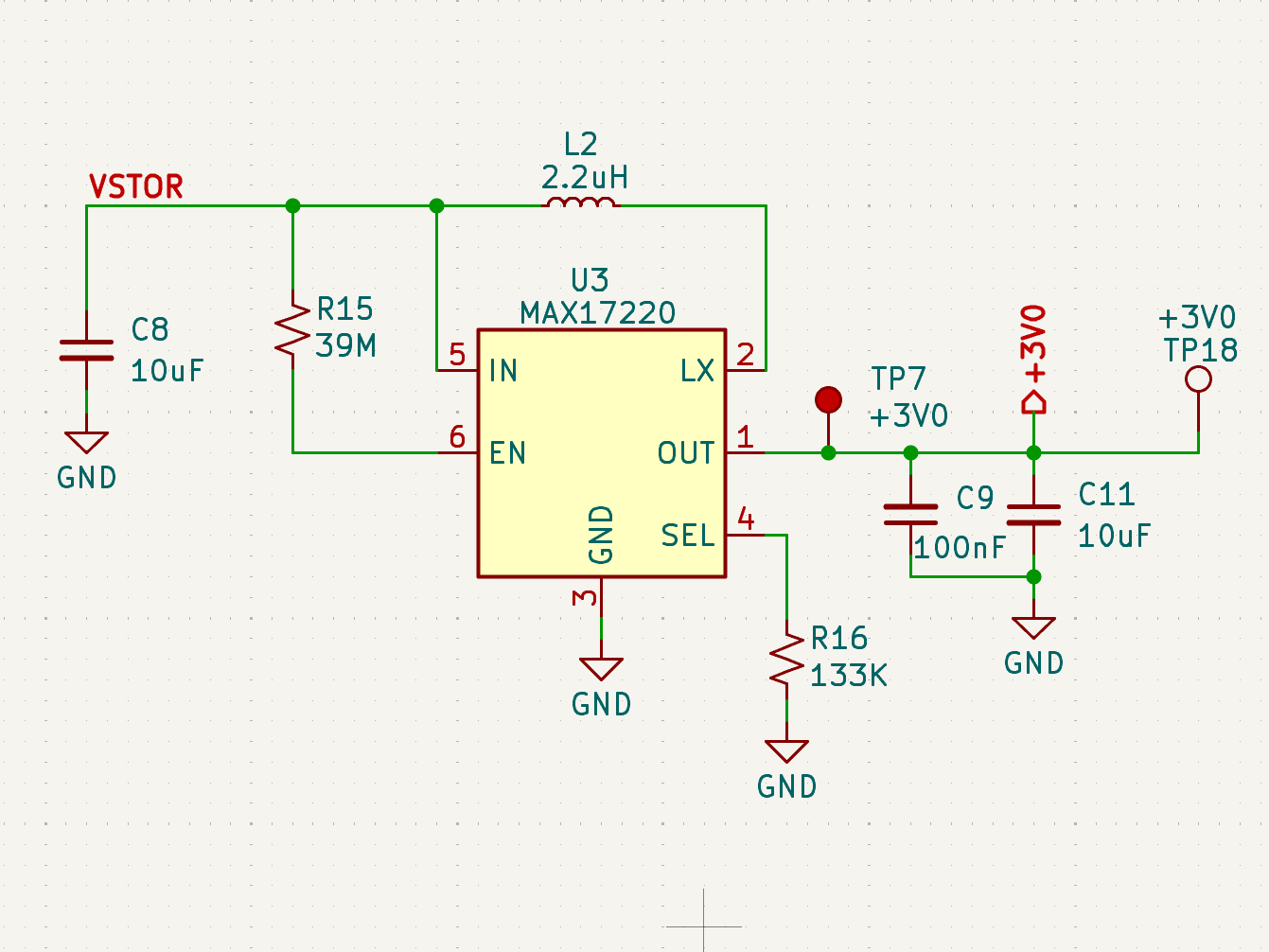
The Benchmark Design: MAX17220 Solar Harvester
The test circuit is a micropower boost converter based on Maxim's MAX17220 (+3V0 output) engineered for solar energy harvesting on an 18 × 14 mm outline (fair pure-auto):
- U3: MAX17220 in WLP-6 (~1.42 × 0.89 mm, 0.4 mm pitch).
- L2: 2.2 µH power inductor (0805 footprint).
- C8: 10 µF input capacitor (VSTOR to GND).
- C9 & C11: 100 nF high-frequency bypass + 10 µF bulk output capacitors (+3V0 to GND).
- R15 & R16: 39 MΩ enable pull-up and 133 kΩ output select resistor.
- Fab Floor: Standard JLCPCB 2-layer rules (0.127 mm trace / space, 0.3 mm drill, 0.6 mm annular ring).

The Physics: Why Switching Regulators Punish Bad Geometry
In high-speed digital design, traces can often be modeled as logical topology. In switching converters, physical geometry dictates analog survival.
When the internal low-side MOSFET of a synchronous boost converter opens, current commutates almost instantaneously through the synchronous rectifier into the output capacitors (Cout) and returns back into the IC ground pin.
This loop carries rapid di / dt switching transitions:
V_spike = L_loop · (di / dt)
A typical surface PCB trace introduces ~1 nH of parasitic inductance per millimeter.
- In Astra's layout: The output capacitors (C9 and C11) were dumped on the opposite side of the chip. The +3V0 rail and GND return travel over 6 millimeters across the board. That ~10–12 nH of loop inductance causes severe voltage ringing, switch-node overshoots that can break the silicon, and massive radiated EMI.
- In the Hand layout: The designer oriented C9 and C11 vertically right against pins 1 (OUT) and 3 (GND). Total loop length is under 1.5 mm.
Experiment 1: What Happens if Fragua Runs Completely Unassisted?
To test the limits of black-box placement, we gave Fragua the same unconstrained challenge: "Here is the netlist; auto-place and route from scratch with zero hints."
Fragua's simulated annealing engine (auto-place seed=42) optimizes global wirelength (HPWL) and bounding overlaps. On a tiny 15 × 12 mm board without domain hints:
- It drifted U3 into the board corner.
- It allowed a courtyard collision between U3 and L2.
- The autorouter could only complete 2 of the 6 nets.
The takeaway: Generic optimization algorithms do not know what a switching converter is. Tools that advertise "zero-prompt unassisted layout" inevitably violate basic electrical laws.
Experiment 2: The Fragua Approach (Agent Steers, Engine Solves)
Fragua is designed around a simple contract: The human or AI agent steers physical constraints, and Fragua's local Go engine executes in milliseconds with strict DRC guarantees.
1. Same BOM as Hand (WLP-6)
The Hand/Astra photos use Maxim's WLP-6 (~1.42 × 0.89 mm, 0.4 mm pitch). Fragua generates that land with density-N courtyards:
lib-gen max17220_wlp6 family=wlp pins=6 pitch=0.4 body=0.89 body_len=1.42 pad=0.24
The netlist matches Hand: U3, L2, C8, C9 + C11, R15 (EN), R16 (SEL) — no single-Cout shortcut, no SOT-23 stand-in.
2. Anchor U3, Then Pure Auto
Only the IC is placed. Power-island seating puts L2 on the LX/VSTOR face and keeps R16 off the inductor body; the router finishes every net:
place U3 9 7
auto-place seed=42
route max_seconds=180
auto-pour
stitch
3. The Execution
Running the script above (fair Hand BOM, WLP-6):
- Routing Time: ~15 ms for the route step (full place→route→pour→stitch stays under a second).
- Completion: 6/6 nets with 0 DRC errors and 0 DRC warnings.
- Cout: C9 (100 nF) + C11 (10 µF) on OUT/GND — same dual-cap BOM as Hand.
- Packages: WLP-6 U3 (not SOT-23), 0805 L2, 0603 passives — same sizes as the tweet boards.
- No hand copper: only
place U3; everything else is auto-place / route / pour / stitch.
The Dealbreaker: 86 Millisecond Incremental Edits
Alperen noted that Astra's biggest barrier was incremental editing: "I tried to add the test point later and asked Astra to route it for me quickly, it took it 4 minutes."
We tested modifying the board in Fragua:
move TP7 12.5 3.0
route max_seconds=5
Console output:
ok move: moved TP7 to 12.50,3.00
ok route: route: 6/6 nets ok, 35 traces, 7 vias, 64.7 mm copper, 86 ms
ok drc: drc: 0 errors
86 milliseconds.
Astra burned minutes on a single edit. Fragua pure-auto on the fair Hand BOM finishes 6/6 nets in ~15 ms (place U3 → auto-place → route → pour → stitch) with DRC 0 — no hand copper.
Benchmark Summary
| Check | Hand Routed | Astra ("Vibe") | Fragua (Unassisted) | Fragua (pure auto) |
|---|---|---|---|---|
| Autoroute Time | 15–30 min manual | ~5 minutes | ~10 seconds | ~15 ms route |
| Incremental Edit Time | ~1 min manual | ~4 minutes | N/A | same BOM as Hand (WLP-6) |
| Nets Completed | 6/6 (100%) | 6/6 (100%) | 2/6 (33%) | 6/6 (100%) |
| Switch Node (LX) Vias | 0 vias (top copper) | 0 vias (snaked) | Unrouted | 0 vias (top copper direct) |
| Cout Proximity | ~1.5 mm | > 5.0 mm (opposite side) | Scattered | C9+C11 local (fair BOM) |
| High di/dt Loop Area | Minimal | Severe (ringing risk) | N/A | Minimal |
| DRC / ERC | Clean | Clean (cosmetic flaws) | 8 errors | 0 errors, 0 warnings |
| Manufacturing Pack | JLCPCB | Gerber export | Fails (unrouted) | JLCPCB zip generated |
Reproduce in 25 Lines
You can run this exact script in Fragua right now (bench/boost-max17220-fair/script.txt):
outline 18 14 radius=1
fab-rules jlcpcb
class ground pour=both
class power width=0.35
class switch width=0.35

lib-gen max17220_wlp6 family=wlp pins=6 pitch=0.4 body=0.89 body_len=1.42 pad=0.24
lib-gen l_2016 family=chip size=0805 kind=l
lib-gen c_0603 family=chip size=0603 kind=c
lib-gen r_0603 family=chip size=0603 kind=r

sym U3 ic key=max17220_wlp6
  pin A1 L OUT role=power_out
  pin A2 R BATT role=power_in
  pin B1 L GND role=power_in
  pin B2 R LX role=output
  pin C1 L EN role=passive
  pin C2 R SEL role=passive
sym L2 inductor key=l_2016
sym C8 capacitor key=c_0603
sym C9 capacitor key=c_0603
sym C11 capacitor key=c_0603
sym R15 resistor key=r_0603
sym R16 resistor key=r_0603

net GND U3.GND C8.2 C9.2 C11.2 R16.2 class=ground
net VSTOR U3.BATT L2.2 C8.1 R15.1 class=power
net +3V0 U3.OUT C9.1 C11.1 class=power
net LX U3.LX L2.1 class=switch
net SEL U3.SEL R16.1
net EN U3.EN R15.2

erc
palette U3 max17220_wlp6
palette L2 l_2016 value=2.2uH
palette C8 c_0603 value=10uF
palette C9 c_0603 value=100nF
palette C11 c_0603 value=10uF
palette R15 r_0603 value=39M
palette R16 r_0603 value=133k

place U3 9 7
auto-place seed=42
route max_seconds=180
auto-pour
stitch
drc
status
Conclusion: The Future of AI in Hardware
"Vibe routing" without physics-aware constraints is an illusion for power electronics and high-speed design.
The winning model is not replacing engineers with slow, unpredictable black boxes. It is giving engineers and their AI agents a blazingly fast, deterministic CAD engine that respects manufacturing constraints, streams progress live, and completes routes in milliseconds.
Fragua is open source and written in pure Go. Inspect the code, try the script, or run the desktop UI at github.com/kidandcat/fragua.